
Products
Environmental Monitoring Sensor HD-S90
Specifications
Nine Elements Sensor
HD-S90
File version:V1.4
product description
1.1 Product overview
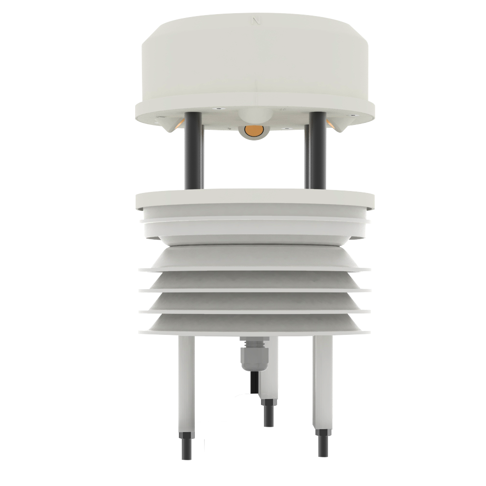
This all-in-one weather station can be widely used in environmental detection, integrating wind speed, wind direction, temperature and humidity, noise collection, PM2.5 and PM10, atmospheric pressure, and light. The equipment adopts standard MODBUS-RTU communication protocol, RS485 signal output, and the communication distance can reach up to 2000 meters. Data can be uploaded to the customer's monitoring software or PLC configuration screen through 485 communications. It also supports secondary development.
With the built-in electronic compass selection device, there is no longer a position requirement during installation, and only the horizontal installation is required. It is suitable for use in mobile occasions such as marine ships, automobile transportation, etc., and there is no direction requirement during installation.
This product is widely used in various occasions that need to measure environmental temperature and humidity, noise, air quality, atmospheric pressure, light, etc. It is safe and reliable, beautiful in appearance, easy to install, and durable.
1.2 Features
This product is small in size and light in weight. It is made of high-quality anti-ultraviolet materials and has a long service life. It uses a high-sensitivity probe with stable signal and high accuracy. The key components adopt imported components, which are stable and reliable, and have the characteristics of wide measurement range, good linearity, good waterproof performance, convenient use, easy installation, and long transmission distance.
◾ It adopts an integrated design with multiple collection devices and is easy to install.
◾ Wind speed and direction are measured by ultrasonic principle, no start-up wind speed limit, zero wind speed work, no angle limit, 360° omni-directional, wind speed and wind direction data can be obtained at the same time.
◾ Noise collection, accurate measurement, the range is as high as 30dB~120dB.PM2.5 and PM10
◾ Simultaneous acquisition, range: 0-1000ug/m3, resolution 1ug/m3, unique dual-frequency data acquisition and automatic calibration technology, consistency can reach ±10%.
◾ Measuring the environmental temperature and humidity, the measuring unit is imported from Switzerland, and the measurement is accurate.
◾ Wide range 0-120Kpa air pressure range, applicable to various altitudes.
◾ Use dedicated 485 circuit, stable communication.
Equipment with built-in electronic compass, no direction requirements during installation, horizontal installation.
1.3 Main technical index
|
DC power supply (default) |
10-30VDC |
|
|
Maximum power consumption |
RS485 output |
1.2W |
|
Precision |
Wind speed |
±(0.2m/s±0.02*v)(v is the true wind speed) |
|
Wind direction |
±3° |
|
|
Humidity |
±3%RH(60%RH,25℃) |
|
|
Temperature |
±0.5℃(25℃) |
|
|
Atmospheric pressure |
±0.15Kpa@25℃ 75Kpa |
|
|
Noise |
±3db |
|
|
PM10 PM2.5 |
±10%(25℃) |
|
|
Light intensity |
±7%(25℃) |
|
|
Range |
Wind speed |
0~60m/s |
|
Wind direction |
0~359° |
|
|
Humidity |
0%RH~99%RH |
|
|
Temperature |
-40℃~+80℃ |
|
|
Atmospheric pressure |
0-120Kpa |
|
|
Noise |
30dB~120dB |
|
|
PM10 PM2.5 |
0-1000ug/m3 |
|
|
Light intensity |
0~20万Lux |
|
|
Long-term stability |
Temperature |
≤0.1℃/y |
|
Humidity |
≤1%/y |
|
|
Atmospheric pressure |
-0.1Kpa/y |
|
|
Noise |
≤3db/y |
|
|
PM10 PM2.5 |
≤1%/y |
|
|
Light intensity |
≤5%/y |
|
|
Response time |
Wind speed |
1S |
|
Wind direction |
1S |
|
|
Temp & Hum |
≤1s |
|
|
Atmospheric pressure |
≤1s |
|
|
Noise |
≤1s |
|
|
PM10 PM2.5 |
≤90S |
|
| Light intensity |
≤0.1s |
|
|
Output signal |
RS485 output |
RS485 (standard Modbus communication protocol) |
1.4 Product model
| RS- |
Company code |
||||
| FSXCS- |
Ultrasonic integrated weather station |
||||
| N01- |
485 communication (standard Modbus-RTU protocol) |
||||
| 1- |
One-piece housing |
||||
| None |
No built-in electronic compass |
||||
| CP |
Built-in electronic compass function |
||||
Equipment size
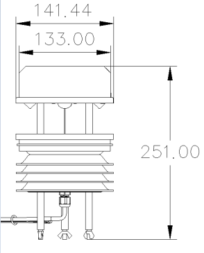
Equipment size chart(UNIT:mm)
Configuration softwareEquipment installation instructions installation and use
3.1 Inspection before equipment installation
Equipment List:
■One integrated weather station equipment
■A pack of mounting screws
■Warranty card, certificate of conformity
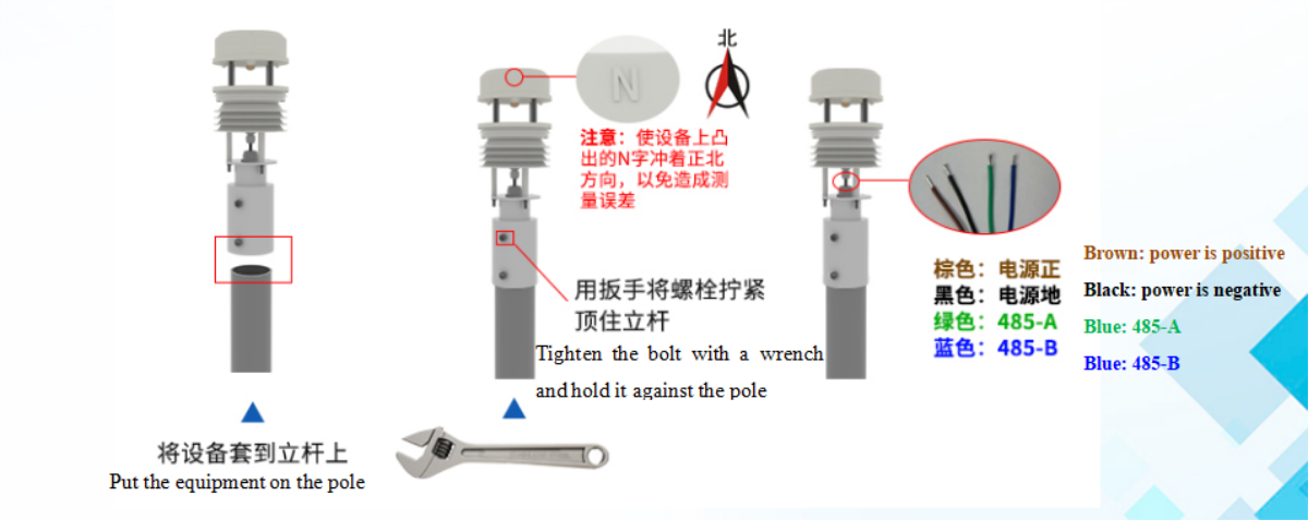
3.2 Installation method
The installation of equipment without electronic compass is shown in the figure below, and the equipment with built-in electronic compass only needs to be installed horizontally.
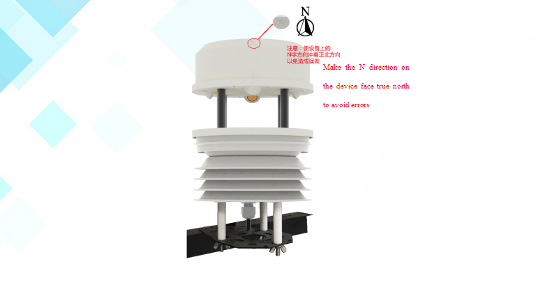
Hugging seat installation:
Note: Make the N word protruding on the device face true north to avoid measurement errors
Beam installation:
3.3 Interface Description
DC power supply 10-30V power supply. When wiring the 485 signal line, pay attention to the two wires A/B not to be reversed, and the addresses of multiple devices on the bus cannot be conflicted.
|
|
Line color |
Illustrate |
|
Power supply |
Brown |
Power is positive(10-30V DC) |
|
Black |
Power is negative |
|
|
Communication |
Green |
485-A |
|
Blue |
485-B |
3.4 485 field wiring instructions
When multiple 485 devices are connected to the same bus, there are certain requirements for field wiring. For details, please refer to the "485 Device Field Wiring Manual" in the information package.
Configuration software installation and use
4.1 Software selection
Open the data package, select "Debugging software" --- "485 parameter configuration software", find "485 parameter configuration tool"
4.2 Parameter settings
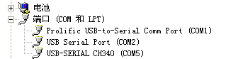
①、Select the correct COM port (check the COM port in "My Computer—Properties—Device Manager—Port"). The following figure lists the driver names of several different 485 converters.
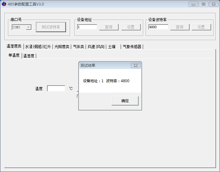
②、Connect only one device separately and power it on, click the test baud rate of the software, the software will test the baud rate and address of the current device, the default baud rate is 4800bit/s, and the default address is 0x01.
③、Modify the address and baud rate according to the needs of use, and at the same time query the current function status of the device.
④、If the test is unsuccessful, please recheck the equipment wiring and 485 driver installation.
485 parameter configuration tool
Communication protocol
5.1 Basic communication parameters
|
Code |
8-bit binary |
|
Data bit |
8-bit |
|
Parity bit |
None |
|
Stop bit |
1-bit |
|
Error checking |
CRC(Redundant cyclic code) |
|
Baud rate |
Can be set to 2400bit/s, 4800bit/s, 9600 bit/s, the factory default is 4800bit/s |
5.2 Data frame format definition
Adopt Modbus-RTU communication protocol, the format is as follows:
Initial structure ≥ 4 bytes of time
Address code = 1 byte
Function code = 1 byte
Data area = N bytes
Error check = 16-bit CRC code
Time to end structure ≥ 4 bytes
Address code: the starting address of the transmitter, which is unique in the communication network (factory default 0x01).
Function code: The command function instruction issued by the host, this transmitter only uses function code 0x03 (read register data).
Data area: The data area is the specific communication data, pay attention to the high byte of the 16bits data first!
CRC code: two-byte check code.
Host query frame structure:
|
Address code |
Function code |
Register start address |
Register length |
Check code low byte |
Check code high byte |
|
1 byte |
1 byte |
2 bytes |
2 bytes |
1 byte |
1 byte |
Slave response frame structure:
|
Address code |
Function code |
Number of valid bytes |
Data area |
Data area two |
Data N area |
Check code low byte |
Check code high byte |
|
1 byte |
1 byte |
1 byte |
2 bytes |
2 bytes |
2 bytes |
1 byte |
1 byte |
5.3 Communication register address description
The contents of the register are shown in the following table (support 03/04 function code):
|
Register address |
PLC or configuration address |
Content |
Operation |
Definition description |
|
500 |
40501 |
Wind speed value |
Read only |
100 times the actual value |
|
501 |
40502 |
Wind force |
Read only |
Actual value (The wind level value corresponding to the current wind speed) |
|
502 |
40503 |
Wind direction (0-7 files) |
Read only |
Actual value (the direction of true north is 0, the value is increased clockwise, and the value of true east is 2) |
|
503 |
40504 |
Wind direction(0-360°) |
Read only |
Actual value (the direction of true north is 0° and the degree increases clockwise, and the direction of true east is 90°) |
|
504 |
40505 |
Humidity value |
Read only |
10 times the actual value |
|
505 |
40506 |
Humidity value |
Read only |
10 times the actual value |
|
506 |
40507 |
Noise value |
Read only |
10 times the actual value |
|
507 |
40508 |
PM2.5 value |
Read only |
Actual value |
|
508 |
40509 |
PM10 value |
Read only |
Actual value |
|
509 |
40510 |
Atmospheric pressure value (unit Kpa,) |
Read only |
10 times the actual value |
|
510 |
40511 |
High 16-bit value of Lux value of 20W | Read only |
Actual value |
|
511 |
40512 |
High 16-bit value of Lux value of 20W | Read only |
Actual value |
5.4 Communication protocol example and explanation
5.4.1 example:Read the real-time wind speed value of the transmitter device (address 0x01)
Interrogation frame
|
Address code |
Function code |
Initial address |
Data length |
Check code low byte |
Check code high byte |
|
0x01 |
0x03 |
0x01 0xF4 |
0x00 0x01 |
0x C4 |
0x04 |
Reply frame
|
Address code |
Function code |
Returns the number of valid bytes |
Wind speed value |
Check code low byte | Check code high byte |
|
0x01 |
0x03 |
0x02 |
0x00 0x7D |
0x78 |
0x65 |
Real-time wind speed calculation:
Wind speed:007D (Hexadecimal)= 125 => Wind speed = 1.25 m/s
5.4.2 example:Read the wind direction value of the transmitter device (address 0x01)
Interrogation frame
|
Address code |
Function code |
Initial address |
Data length |
Check code low byte |
Check code low byte |
|
0x01 |
0x03 |
0x01 0xF6 |
0x00 0x01 |
0x65 |
0xC4 |
Reply frame
|
Address code |
Function code |
Returns the number of valid bytes |
Wind speed value |
Check code low byte | Check code high byte |
|
0x01 |
0x03 |
0x02 |
0x00 0x02 |
0x39 |
0x85 |
Real-time wind speed calculation:
Wind speed:0002 (Hexadecimal)= 2 => Wind speed = East wind
5.4.3 example:Read the temperature and humidity value of the transmitter device (address 0x01)
Interrogation frame
|
Address code |
Function code |
Initial address |
Data length |
Check code low bit |
High bit of check code |
|
0x01 |
0x03 |
0x01 0xF8 |
0x00 0x02 |
0x44 |
0x06 |
Reply frame(For example, the temperature is -10.1℃ and the humidity is 65.8%RH)
|
Address code |
Function code |
Number of valid bytes |
Humidity value |
Temperature value |
Check code low bit |
High bit of check code |
|
0x01 |
0x03 |
0x04 |
0x02 0x92 |
0xFF 0x9B |
0x5A |
0x3D |
Temperature: upload in the form of complement code when the temperature is lower than 0℃
0xFF9B (Hexadecimal)= -101 => temperature = -10.1℃
Humidity:
0x0292(Hexadecimal)=658=> humidity = 65.8%RH
Common problems and solutions
The device cannot connect to the PLC or computer
Possible reason:
1) The computer has multiple COM ports and the selected port is incorrect.
2) The device address is wrong, or there are devices with duplicate addresses (the factory default is all 1).
3) The baud rate, check method, data bit, and stop bit are wrong.
4) The host polling interval and waiting response time are too short, and both need to be set above 200ms.
5) The 485 bus is disconnected, or the A and B wires are connected reversely.
6) If the number of equipment is too much or the wiring is too long, power supply should be nearby, add a 485 booster, and add a 120Ω terminal resistance at the same time.
7) The USB to 485 driver is not installed or damaged.
8) Equipment damage.


-

Phone
-

E-mail
-

Whatsapp
-

Top