
Products

Environmental Monitoring Sensor HD-S70
Specifications
Seven Elements Sensor
HD-S70
File version:V4.2
product description
1.1 Overview
This one-piece shutter can be widely used in environmental detection, integrating noise collection, PM2.5 and PM10, temperature and humidity, atmospheric pressure, and light. It is installed in a louver box, the equipment adopts standard MODBUS-RTU communication protocol, RS485 signal output, and the maximum communication distance can reach 2000 meters (measured). This transmitter is widely used in various occasions that need to measure environmental temperature and humidity, noise, air quality, atmospheric pressure and illumination, etc. It is safe and reliable, beautiful in appearance, easy to install, and durable.
1.2 Features
This product is small in size, light in weight, made of high-quality anti-ultraviolet materials, long service life, high-sensitivity probe, stable signal, high precision. The key components adopt imported components, which are stable and reliable, and have the characteristics of wide measurement range, good linearity, good waterproof performance, convenient use, easy installation, and long transmission distance.
◾ Noise collection, accurate measurement, the range is as high as 30dB~120dB.
◾ PM2.5 and PM10 are collected at the same time, range: 0-1000ug/m3, resolution 1ug/m3, unique dual-frequency data collection and automatic calibration technology, consistency can reach ±10%.
◾ Measure the environmental temperature and humidity, the measuring unit is imported from Switzerland, the measurement is accurate, and the range is -40~120 degrees.
◾ Wide range 0-120Kpa air pressure range, applicable to various altitudes.
◾ The light collection module adopts a high-sensitivity photosensitive probe, and the light intensity range is 0~200,000 Lux.
◾ Use dedicated 485 circuit, stable communication, 10~30V wide voltage range power supply.
1.3 Main Technical index
|
DC power supply(default) |
10-30VDC |
|
|
Maximum power consumption |
RS485 output |
0.8W |
|
Precision |
Temperature |
±3%RH(60%RH,25℃) |
|
Humidity |
±0.5℃(25℃) |
|
|
Light intensity |
±7%(25℃) |
|
|
Atmospheric pressure |
±0.15Kpa@25℃ 75Kpa |
|
|
Noise |
±3db |
|
|
PM10 PM2.5 |
±10%(25℃) |
|
|
Range |
Humidity |
0%RH~99%RH |
|
Temperature |
-40℃~+120℃ |
|
|
Light intensity |
0~20万Lux |
|
|
Atmospheric pressure |
0-120Kpa |
|
|
Noise |
30dB~120dB |
|
|
PM10 PM2.5 |
0-1000ug/m3 |
|
|
Long-term stability |
Temperature |
≤0.1℃/y |
|
Humidity |
≤1%/y |
|
|
Light intensity |
≤5%/y |
|
|
Atmospheric pressure |
-0.1Kpa/y |
|
|
Noise |
≤3db/y |
|
|
PM10 PM2.5 |
≤1%/y |
|
|
Response time |
Humidity& Temperature |
≤1s |
| Light intensity |
≤0.1s |
|
| Atmospheric pressure |
≤1s |
|
| Noise |
≤1s |
|
| PM10 PM2.5 |
≤90S |
|
|
Output signal |
RS485 output |
RS485(Standard Modbus communication protocol) |
Installation instructions
2.1 Checklist before installation
Equipment List:
■1 transmitter
■USB to 485(Optional)
■Warranty card, certificate of conformity, after-sales service card, etc.
2.2 Interface Description
Wide voltage power input range 10~30V. When wiring the 485 signal line, pay attention to the two lines A and B not to be reversed, and the addresses of multiple devices on the total wire must not conflict.
|
|
Thread color |
Illustrate |
|
Power supply |
Brown |
Power is positive(10~30V DC) |
|
Black |
Power is negative |
|
|
Communication |
Yellow |
485-A |
|
Blue |
485-B |
2.3 485 field wiring instructions
When multiple 485 devices are connected to the same total wire, there are certain requirements for field wiring. For details, please refer to the "485 Device Field Wiring Manual" in the information package.
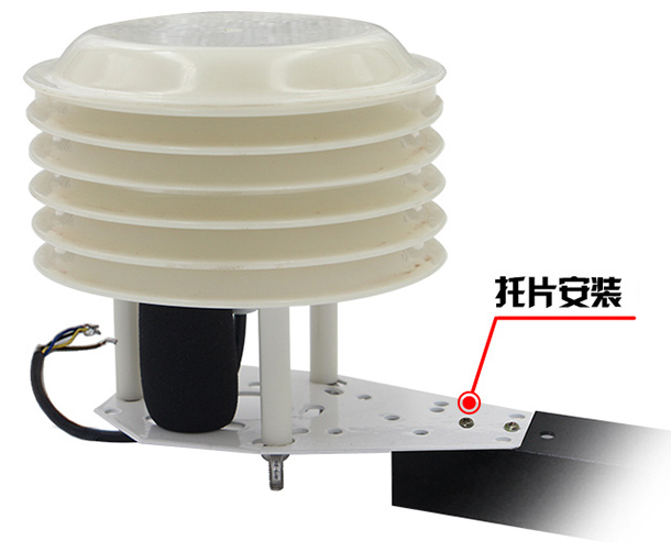
2.4 Installation example
Configuration software installation and use
3.1 Software selection
Open the data package, select "Debugging software" --- "485 parameter configuration software", find "485 parameter configuration tool"
3.2 Parameter settings
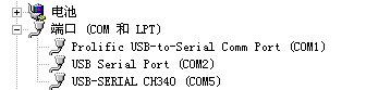
①、Select the correct COM port (check the COM port in "My Computer—Properties—Device Manager—Port"). The following figure lists the driver names of several different 485 converters.
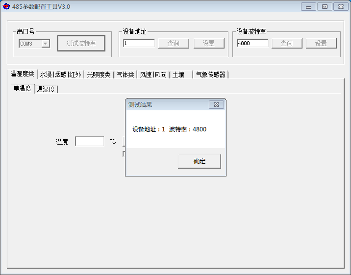
②、Connect only one device separately and power it on, click the test baud rate of the software, the software will test the baud rate and address of the current device, the default baud rate is 4800bit/s, and the default address is 0x01.
③、Modify the address and baud rate according to the needs of use, and at the same time query the current function status of the device.
④、If the test is unsuccessful, please recheck the equipment wiring and 485 driver installation.
485 parameter configuration tool
Communication Protocol
4.1 Basic communication parameters
|
Code |
8-bit binary |
|
Data bit |
8-bit |
|
Parity bit |
None |
|
Stop bit |
1-bit |
|
Error checking |
CRC(Redundant cyclic code) |
|
Baud rate |
Can be set to 2400bit/s, 4800bit/s, 9600 bit/s, the factory default is 4800bit/s |
4.2 Data frame format definition
Adopt Modbus-RTU communication protocol, the format is as follows:
Initial structure ≥4 bytes of time
Address code = 1 byte
Function code = 1 byte
Data area = N bytes
Error check = 16-bit CRC code
Time to end structure ≥ 4 bytes
Address code: the starting address of the transmitter, which is unique in the communication network (factory default 0x01).
Function code: the command function instruction issued by the host, this transmitter only uses function code 0x03 (read register data).
Data area: The data area is the specific communication data, pay attention to the high byte of the 16bits data first!
CRC code: two-byte check code.
Host query frame structure:
|
Address code |
Function code |
Register start address |
Register length |
Check code low bit |
High bit of check code |
|
1 byte |
1 byte |
2 bytes |
2 bytes |
1 byte |
1 byte |
Slave response frame structure:
|
Address code |
Function code |
Number of valid bytes |
Data area |
Second data area |
Nth data area |
Check code |
|
1 byte |
1 byte |
1 byte |
2 bytes |
2 bytes |
2 bytes |
2 bytes |
4.3 Communication register address description
The contents of the register are shown in the following table (support 03/04 function code):
| Register address | PLC or configuration address | Content | Operation |
| 500 | 40501 | Humidity value (10 times the actual value) | Read only |
| 501 | 40502 | Temperature value (10 times the actual value) | Read only |
| 502 | 40503 | Noise value (10 times the actual value) | Read only |
| 503 | 40504 | PM2.5 (actual value) | Read only |
| 504 | 40505 | PM10(actual value) | Read only |
| 505 | 40506 | Atmospheric pressure value (unit Kpa, actual value 10 times) | Read only |
| 506 | 40507 | The high 16-bit value of the Lux value of 20W (actual value) | Read only |
| 507 | 40508 | The low 16-bit value of the Lux value of 20W (actual value) | Read only |
4.4 Communication protocol example and explanation
4.4.1 Inquire about equipment temperature and humidity
For example, inquire about the temperature and humidity value: the device address is 03
|
Address code |
Function code |
Initial address |
Data length |
Check code low bit |
High bit of check code |
|
0x03 |
0x03 |
0x01 0xF4 |
0x00 0x02 |
0x85 |
0xE7 |
Response frame (for example, the temperature is -10.1℃ and the humidity is 65.8%RH)
|
Address code |
Function code |
Number of valid bytes |
Humidity value |
Temperature value |
Check code low bit |
High bit of check code |
|
0x03 |
0x03 |
0x04 |
0x02 0x92 |
0xFF 0x9B |
0x79 |
0xFD |
Temperature: upload in the form of complement code when the temperature is lower than 0℃
0xFF9B (Hexadecimal)= -101 => Temperature = -10.1℃
Humidity:
0x0292(Hexadecimal)=658=> Humidity = 65.8%RH
Common problems and solutions
The device cannot connect to the PLC or computer
Possible reason:
1) The computer has multiple COM ports and the selected port is incorrect.
2) The device address is wrong, or there are devices with duplicate addresses (the factory default is all 1)
3) The baud rate, check method, data bit, and stop bit are wrong.
4) The host polling interval and waiting response time are too short, and both need to be set above 200ms.
5) The 485 total wire is disconnected, or the A and B wires are connected reversely.
6) If the number of equipment is too large or the wiring is too long, power supply should be nearby, add a 485 booster, and add a 120Ω terminal resistance at the same time.
7) The USB to 485 driver is not installed or damaged.
8) Equipment damage.
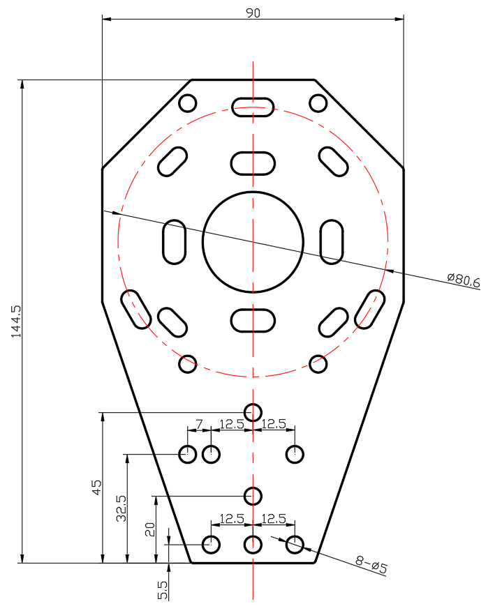
Appendix:Shell size
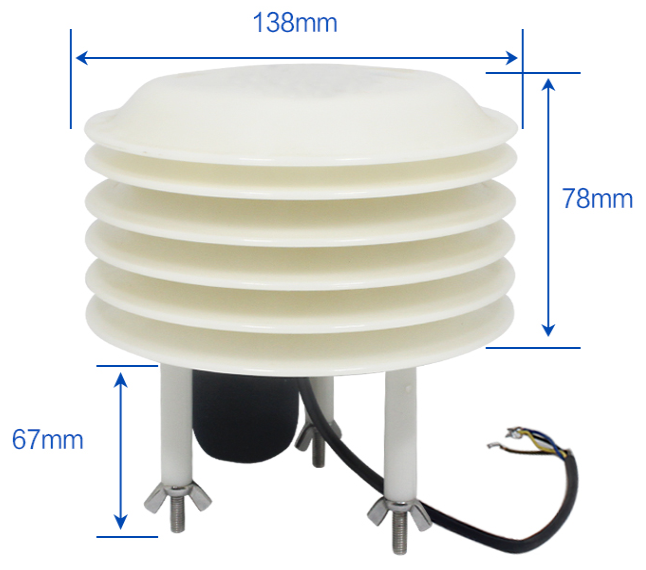


-

Phone
-

E-mail
-

Whatsapp
-

Top